Fixing Riser and Duct Leaks
Duct Work and Riser air leaks can compromise HVAC Energy efficiency and safety/health. What are the Effects of leakage on energy use and even safety? Ductless risers and service risers…

Duct Work and Riser air leaks can compromise HVAC Energy efficiency and safety/health. What are the Effects of leakage on energy use and even safety? Ductless risers and service risers…

Some builders are concerned about making home too airtight Some arguments they give are: “Humans need to breathe, and so does a building.” “We don’t want occupants suffocating—fresh air has…

Under Floor Air Distribution Air Tightness Testing Efficiency Matrix tests to BSRIA BG65-2016 Underfloor Air Distribution (UFAD) systems have become increasingly popular in new commercial buildings worldwide. Efficiency Matrix is…

When aiming to build airtight, the true magic isn’t in the air tightness test itself — it’s in the building design, consistent quality assurance (through air barrier integrity auditing) during…

Not all wall wraps are created equal. Different users have different requirements and expectations for what they want their wrap to do. In most cases we should, and can expect…

Frequently Asked Questions (FAQ) 1. What capability of duct air tightness testing can Efficiency Matrix do? Testing capabilities for builder’s risers (speedpanel/precast/blockwork/riser liner), plenums or sheet metal ducts. 250Pa…
Building performance is the single most important thing for ALL buildings. With poor building envelope performance, comes higher energy consumption. Simply installing more efficient heating and cooling systems does…
Airtightness in large enclosures can get tricky and complicated. We see some pretty questionable things in specifications for the testing of these types of facilities. While these buildings are often…
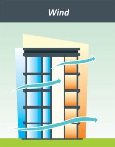
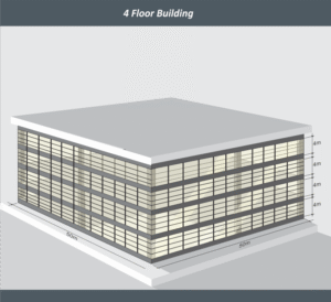
How can we make sense of the mismatch between real-world building performance and regulatory requirements? In this article, we explore how a building’s form and surrounding weather conditions render the…


The Green Building movement in the past few decades has brought in many changes to the construction industry and changed the mindset amongst design professionals. One of the key changes…

Efficiency Matrix and its eCaulkair product are a safe, non-toxic automated application of sealant for rigid ducts or plenums used globally in commercial & domestic air tightness applications. The key ingredient of the…
